|
GSI
KR
FRS
MANUAL
CALIBRATION
NEWS
| |
|
SEcondary
Electron TRAnsmission Monitor |
Introduction
At relativistic
energies, the usual method to determine heavy-ion beam intensities by
measuring the electric current in a beam stop is not easily applicable
due to the long range of charged secondary reaction products that emerge
from the stopping process. At the FRS, a secondary-electron transmission
monitor (SEETRAM) is used to survey the beam intensity almost without
influencing the beam quality. Most of the secondary electrons have
energies of a few eV. The number of electrons per ion at 1 A GeV is
roughly
ne » Z2 / 40. As the secondary
electrons originate from a very thin surface layer so that even at high
beam intensities, space-charge effects are not expected. Therefore, the
secondary-electron current is assumed to be exactly proportional to the
primary-beam current.
SEETRAM and the
associated equipment installed installed
at the FRS target station provide valuable information on the following
topics: |
Spill
structure
For most experiments it is important that the primary-beam intensity is
distributed as homogeneously as possible over the extraction time in
order to avoid unnecessary pile-up rates and dead-time losses. A fast
monitoring of the beam intensity over the extraction time allows
determining the extraction profile. This information helps finding the
optimum tuning of the SIS extraction. |
Extraction
efficiency
The extraction losses lead to activation in the extraction zone.
Therefore, the radioprotection service may demand a reduction of the
beam intensity if the extraction losses exceed a certain level. The
extraction efficiency can be determined by comparing the absolute
intensity of the extracted beam, integrated over one spill, with the
current determined inside SIS before extraction. For this purpose, the
beam monitor needs to be calibrated. |
Normalisation
of production cross sections
For determining absolute production cross sections one needs to know the
total number of projectiles. For this purpose it is necessary to
register the beam intensity with a calibrated beam monitor continuously
during the whole experiment. |
|
Detector
description
SEETRAM
operation is based on the emission of secondary electrons from thin metal foils
by the passage of the projectiles. It consists of one titanium foils of 10
microm
thickness sandwiched between two aluminium foils of 14 microm
thickness each (see Figure 1). Each foil has an diameter of 11.5 cm. They are
mounted perpendicular to the beam axis. The outer foils are connected to a
voltage of +80 V. They and their supporting aluminium rings form the detector
housing. The middle foil is supported by two Teflon rings and is insulated
against other parts of the detector. The foils are curved in order to reduce the
sensitivity to mechanical vibration of the beam line. Secondary electrons
emitted from the middle foil are collected by the two outer foils. The created
current in the middle foil is measured by a Current Digitiser CD1010 developed
at GSI [1].
The
sensitivity of the Current Digitiser is computer-controlled from the control
room with the use of
the NODAL programme[1].
SEETRAM sensitivity ranges from 10-4 to 10-10 Ampere full
scale. The full scale current produces 1 V at the monitor output and 10 KHz at
the digitised output. This means that 1 count corresponds to a charge of Q =
sensitivity×10-4
Coulomb.
|
|
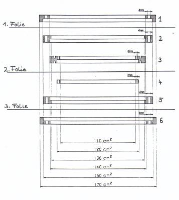
Figure
1. Layout
of SEETRAM [1]. The outer foils are supported by aluminium rings (1, 2, 5,
6). The inner foil is supported and insulated by two Teflon rings (3, 4). |
The
detector device name in the beam diagnostic program (SD-Anwahlprogramm) is
TS1DI4SP.
|
Limits
of application
The
lower limit of the SEETRAM application is given by the condition that the
produced current must be higher than 10-12 Ampere in order to
distinguish the signals from the positive offset of the Current Digitiser (the
same is true for the current signal from the IC01). The corresponding beam
intensity depends on the projectile charge and energy, see figure 20 in ref.
[1]. There is no upper limit for the SEETRAM current. The SC01 is applicable up
to counting
rates of 105 particles/s where saturation effects start to be higher
than 1 %. The particle counting of the IC01 is limited to 104
particles/s due to pile-up in the preamplifier. Also, the particle-counting with
the IC01 is not suitable for ions with Z < 10, because the energy-loss
signals could not be distinguish from the electronic noise. The upper limit of
the current signal from the IC01 is 10-7 Ampere where the
recombination losses become higher than 10 %.
|
|
Possible
problems during the measurements
-
If the beam is not centred on the target, there is a question if all the
projectiles are measured by the SEETRAM, SC01 and IC01. One should check the
beam position using the current grids before the calibration.
-
SEETRAM can only be calibrated in the slow extraction mode. In the case of the
fast extraction, the time structure of spills cannot be seen, but the
integration of the secondary-electron current should work. Moreover, there is
also a danger that the Current Digitiser is saturated because of the presence of
short, high intensity pulses. For this reason, in the case of fast extraction,
one should insert a filter with a time constant in the order of 1 s between the
detector and the input of the
Current Digitiser.
-
The offset of the Current Digitiser must be tuned high enough to ensure that the
digital output of the Current Digitiser never stops. If this happens, any
information on the magnitude of the current during this time is lost.
-
One should compare the number of particles on SEETRAM with those in SIS (ask
operators for beam transformator value). For longer runs it has to be at least
70%, otherwise the radioprotection service may demand a reduction of the beam
intensity because of too high extraction losses. |
|
References
[1]
Christine Ziegler, ‘Aufbau und Einsatz eines Sekundärelektronen-Transmissions-Monitors
zur Messung de absoluten Teilchenstroms am Fragmentseparator’, Diplomarbeit TH
Darmstadt, October 1992.
[2]
B. Jurado, K.-H. Schmidt, K.-H. Behr, ‘Application of a secondary-electron
transmission monitor for high-precision intensity measurements of relativistic
heavy-ion beams’, Nucl.
Instr. Meth. A 483 (2002) 603.
[3]
A. Junghans, H.-G. Clerck, A. Grewe, M. de Jong, J. Müller, K.-H. Schmidt, ‘A
self-calibrating ionisation chamber for the precise intensity calibration of
high-energy heavy-ion beam monitors’, Nucl.
Instr. Meth. A 370 (1996) 312. |
|