LH2-Target
ArCO2
Instruction
Configuration
Low Pressure
P 10
Instruction
Pictures
CF4
Instruction
Pictures
H2
Start of LH2-Target
S0
Change to LD2
Turn off LH2-Target
S0
Alarm
Pictures
September 2003
Start of the S0 LH2-Target
Start the isolation vacuum:
Check the state of the vacuum system (Pressure of the system, PV01, Turbo molecular pump TP01, Rough pump RP01, Vent Valve)
Close the Vent Valve in the pre-vacuum pipe (manual valve in the S0 area close to the RP01)
Open PV01 and switch on RP01
When pressure at IG01 <1 x 10⁻¹ mbar, then switch on TP01
Pumping out the Target:
When the isolation vacuum (IG01) is better than 1 x 10⁻⁴ mbar:
Switch on RP02 and open MV04, MV03 and MV08, after this open MV10 slowly
Read the pressure on PG01: pump out until the pressure is ≤2 x 10⁻² mbar
Close MV04, MV03, MV08 and MV10
Refill of Hydrogen 6.0 (if necessary):
Read pressure at PI01 (at H2-storage tank): if pressure is ≥1.8 bar, then is sufficient Hydrogen available for the liquefaction
If not: activate Hydrogen supply (purge carefully the H2-pipe,
open the manual valves in the H2-cupboard (outside of the hall)
and at the tap S0, open the electromagnetic valve)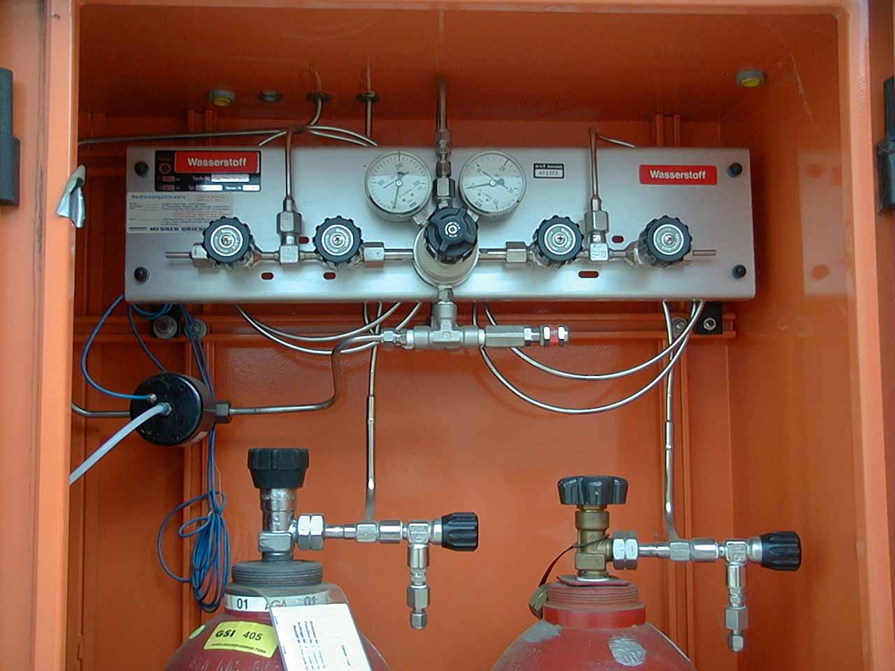
Open MV11 and MV09.
Pump with the RP02 via the MV10 (open the valve carefully and only a little) PI07:~2 bar.
Close MV10 and MV11 (MV09 is kept open)
Close MV03 and MV04
Activate the LN2 Trap and use it!
Fill storage tank (via MV11, MV09, LN2 Trap and MV08)
Open the valve MV01 at the H2 storage tank.
PI03 shows the pressure in the tank, when <1.8 bar: open MV11, open slowly MV08 until pressure has reached ≥1.8 bar.
Close all valves again except the manual valve at the storage tank MV01 and fasten the valve against closing by mistake with the safety ring.
Switch off the H2 Supply; close the valves in the H2 cupboard
The exact pressure of the storage tank is displayed at PT01 (~1.88 bar)
Switch off RP02
Liquefaction:
Switch on compressor (gaseous H2 is now in Target and Condenser).
MV04 and MV03 must be closed.
Open MV08, MV09 and PV02 (switch at the electronic panel)
Test the set point at the PID (Potentiometer left, switch to "int.", Range 10V): it should be adjusted to ~2 - 2.1 Volt.
When liquefaction is started, the pressure in the Target is the same as in the Storage (~1.8 bar), this is the most important parameter and this pressure decreases when Target is filled with liquid H2 to a little bit more than the atmospheric pressure (~1050 – 1070 mbar)
The H2-Flow at the FI is displayed in SCCM (1 SCCM = 1 cm3/min) and is in the beginning of liquefaction high and decreases when reaching the pressure of ~1070 mbar to ~0.9 SSCM
At the "Lake Shore Temperature Controller 330":
Upper display: true value of the Target temperature
Lower display: desired value of the Target temperature (Set Point)
Bar graph display: Heater (appears, when TTarget = Set point)
The liquefaction lasts ~ 5 hours
Important: The "Sondes 1 + 2" are no more available!
The temperature of the liquid H2 is ~20.4 K
Normal reading: PT02: ~1050 mbar
FI01: ~100 – 500 SCCM
The Target is full, when the pressure in the H2 storage tank is decreased to <1080 mbar
If there are problems during filling the Target (e.g. the temperature of the Target remains on 150 K, caused by an impurity of the H2):
Switch off the compressor, let Target warm up and pump out the system completely via RP02 and fill again with pure H2. Purging of the H2 pipe can be done via the gas inlet "H2Gaz" and the excess-pressure-valve RV05 (P>2bar!)
Normal operation (Target is filled with liquid H2):
Switch over the heater regulation to the "high" position with the key "heater(0)" to receive more power for the heater, in the position "medium" or "low" the power will be not sufficient.
The conditions are: TTarget >45 K: no heating
TTarget <45 >21K: "medium"
TTarget <21 K: "high"
Operational data: PT02 (Target): ~1030 to 1050 mbar
PT01 (Storage): ~1075 mbar
FI01: ~100 to 500 SCCM
TTarget: ~20.4 K (= Set point)
In a short time PT01 decreases to ~1050 mbar. Then the automatic control valve Flo01 in the cryo rack is closed. This valve is not absolute tight. Therefore the serial valve PV02 must be closed manually. (Switch at the panel in the electronic rack)
Attention: the flow at the display FI01 will not decreases to 0! There is an indication error of approximately 6 to 7 SCCM.
PV01 can be closed now; the system is working like a cryo pump. The turbo molecular pump is still in operation.
Stop of liquefaction (evaporation of the liquid H2):
Switch off the compressor and open MV04 and MV03
(Eventually adjust the set point at the TC 330 to 45 K)
Open PV01
Click on "Stop" at the PC in the electronic rack
If there is no interaction: insert "quit" in the command line
>FRS1: inkey "FRS"
Press F1 key
Click on "local"
Click on "Stop"
"Experiment stopped" in a red frame appears
After 2 days:
Close MV01 (close to the H2 storage, remove the safety ring!)
Close MV05 and MV11
Open MV06, MV07 and MV09
Switch on pump RP02
Open slowly MV10
Switch on PG01 (Vacuum gauge of the target)
Wait until pressure is <0.1 mbar
Close PV01
Stop pumps TP01 and RP01
Tap on back-pressure valves RV01 to RV05 (in cryo rack) with a soft tool (e.g. plastic hammer)!
CloseMV10
Switch off PG01
Switch off P02
Open N2-cylinder and adjust the reducing valve at approx. 0.4 bar at the PI06
Open MV05 slowly (intermittent) and fill Target at about 1.2 bar
Close MV05
Switch off IG01 (rear panel!)
Switch off screen of the PC
If the rack should be disconnected from electric power:
Insert in the command line of the PC: "quit"
On the screen appears >FRS1 and the PC and all other installation can be switched off.
K.Burkard 21.11.2002