Argon/10%Methan (P10) Gas Supply
ArCO2
Instruction
Configuration
Low Pressure
P 10
Instruction
Pictures
CF4
Instruction
Pictures
H2
Start of LH2-Target
S0
Change to LD2
Turn off LH2-Target
S0
Alarm
Pictures
September 2003
A P10-Gas Supply is located at the Fragment-Separator (FRS).
This system consists of a gas cylinder cabinet outside of the experimental-hall, a stainless-steel gas pipe to the FRS and a pressure-reducer with a following gas-cleaning unit near the gas distribution at the FRS.
The gas cylinder cabinet is located right-handed (south) of the west entrance of the ESR-hall. This cabinet can store 6 gas cylinders with a content of 50 l gas each. There is also the possibility to connect a 12x50l gas bundle instead of the left operated cylinder. The cylinders in operation are connected to the battery pressure reducer BMD 500-35.
Attention:
-
The thread on the cylinder valve and cap nut must be in a faultless condition.
-
Use new gaskets only. Gaskets should not be deformed and should bear no traces of dirt or metal filings.
-
Check that the gaskets are seated correctly inside the spiral connection sockets.
-
The connections to the cylinders have a left-hand thread. (Left-hand threads are signed by a circular groove on the outside of the nut.)
-
Screw on the nut first by hand and then tighten using a forked open jaw wrench. (Be certain to hold down the grip on the spiral pipe when tightening with the wrench!) Don’t use wrench extensions!
-
After changing a gas cylinder or the gas bundle check the leak tightness with a measuring device for the concentration of burnable gases (e.g. SEWERIN EX-TEC SR5) !
Schematic of the battery pressure reducer BMD 500-35:
1 Pressure reducer, 2 admission pressure manometer, 3 high pressure manometer, 4 service gas valve, 5 purge valve, 6 blow-off valve, 7 spiral pipe, 8 filter in spiral, A gas bundle or cylinder, B spare gas cylinder, H control lever
Self-purging: (to remove
outside air, this enters the system when the cylinder is changed)
-
Close all valves
-
Slowly open/close right-hand cylinder valve.
-
Open/close right-hand purging gas valve.
-
Repeat purging cycle 10 times.
-
Slowly open/close left-hand cylinder valve.
-
Open/close left-hand purging gas valve.
-
Repeat purging cycle 10 times
During initial start-up purge the entire unit via the service gas outlet!
Start-up:
If required, implement self-purging before starting up and filling the succeeding pipe system.(See above)
-
Check, whether the purging and waste gas pipes and the spiral have been installed correctly.
-
Close all valves.
-
Turn the change-over switch lever to the right.
-
Slowly open the right-hand/left-hand cylinder valves.
-
Slowly open the right-hand/left-hand service gas valves.
The change-over switch lever always points to the cylinder in use.
Sequence of functions:
Both cylinders are full and connected to the unit. The change-over switch lever is pointing to the right. The cylinders and service gas valves are opened slowly.
Ready for use gas flow from right-hand cylinder
When the right-hand cylinder is empty, the pressure reducer switches automatically to the left-hand cylinder.
Gas flow from left-hand cylinder right cylinder is empty
The left-hand cylinder is now providing the gas supply, the back pressure decreases slightly.
Gas flow from left-hand cylinder cylinder replacement right
To ensure a continuous supply of gas, the right-hand cylinder should be replaced soon. To do this, the change-over switch lever is switched to the left-hand side. The back pressure increases slightly.
For cylinder replacement the cylinder valve on the right hand side are closed. The residual pressure is released by opening (and closing) the purging gas valve. The new cylinder is connected to the unit.

Cylinder is empty gas flow from right-hand cylinder
The gas supply is still being provided by the left-hand cylinder. Once it is empty, automatic change-over to the right hand cylinder occurs. Back pressure decreases slightly as a result.
The entire procedure can be repeated from the start once the change-over switch has been switched back to the right-hand side and the left-hand cylinder has been replaced.
The described change in back pressure during control lever switching and automatic change-over is in accordance with principle and is required for automatic change-over.
Cylinder replacement:
Cylinder replacement takes place after one of the two cylinders has emptied. It is assumed that the control lever is pointing to the empty cylinder (note the manometer reading). The cylinder should be replaced in due time to ensure an uninterrupted supply of gas. Our battery pressure reducer is equipped with contact manometers and the ‘gas shortage’ is signaled at the gas distribution by LEDs for the corresponding cylinder.
-
Switch the change-over switch lever to the side opposite the cylinder which is to be replaced: if the right-hand cylinder is to be replaced, switch the lever to the left-hand side and vice versa. The change-over switch lever always points at first to the cylinder providing the gas supply. Now replace the cylinder:
-
Close the service gas valve and the cylinder valve on the gas cylinder.
-
Release residual pressure via the purging gas valve.
-
Disconnect the connecting spiral from the cylinder valve.
-
Connect up the new service gas cylinder.
-
If necessary, implement self-purging on the side where the new cylinder is located before putting the fitting back into operation.
-
Open the cylinder and service gas valves.
-
The newly connected cylinder is now ready for use.
Shut-off:
For a short interruption of the gas intake, closing the service gas valve is sufficient. For longer periods, the cylinder valve must be closed.
Warning:
For safety reasons, always close the cylinder valve!
During dismantling of the entire unit note:
Decompress pressure regulators and pipes by discharging the gas via the consumer. The indicators on the admission and back pressure manometers must rest fully at ‘0’.
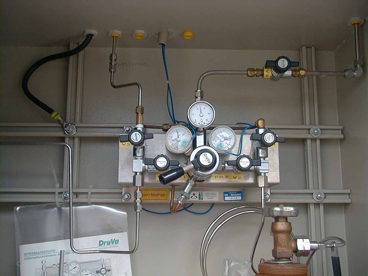
Gas pipe, secondary pressure reducer and gas-cleaning unit:
The gas pipe can be closed at both ends by two valves. These valves should be closed for periods of longer interruptions of the gas intake. The pressure in the gas pipe is normally adjusted at about 6 bar. The pressure for the gas distribution should not exceed 1.5 bar, so a second pressure reducer at the entrance of the gas-cleaning unit reduces the gas pressure at about 1.3 bar typically.
The gas-cleaning unit consists of 3 cartridges in series connection. The both big cartridges removes oxygen and water from the gas, the third one, a small type with a glass envelope, is used to indicates by a change in colour, that the gas-cleaning unit is charged full with oxygen respectively water. In this case, all cartridges must be replaced as soon as possible.
Capacities:
Oxisorb: 9 l Oxygen and 9 l water vapour
Hydrosorb: 100 l water vapour
Max. Flow: 10 m3 / h
Note: Maintenance and repairs must only be done by our technical staff or by the manufacturer.
K.Burkard 18.06.2003